

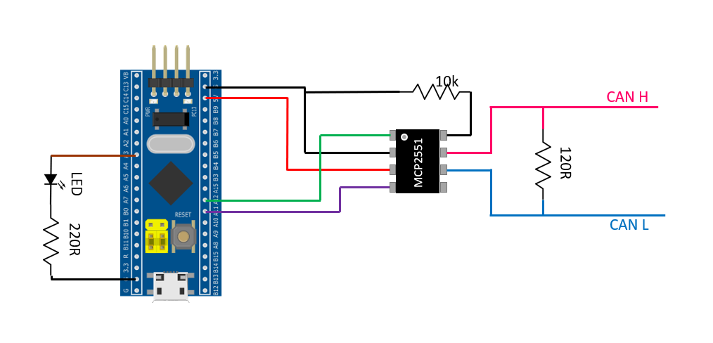
CAN BUS is an easy to use protocol with just 2 wires and 2 termination resistor. We can connect upto 127 devices on CAN Bus.
In this tutorial we are going to use the following parts:
- Blue Pill Board – STM32F103C8T6
- MCP2551 – CAN Tranceiver
- 120R Resistor
- 10K Resistor
- 220R Resistor
- 5MM LED
Connect the parts like it is shown in the picture below
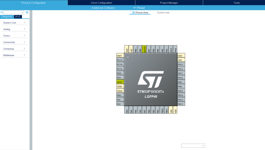
Once the wiring is done download and install STM32CubeIDE . After installing create a new project and open Device Configuration Tool . You will be greeted with a screen like below.
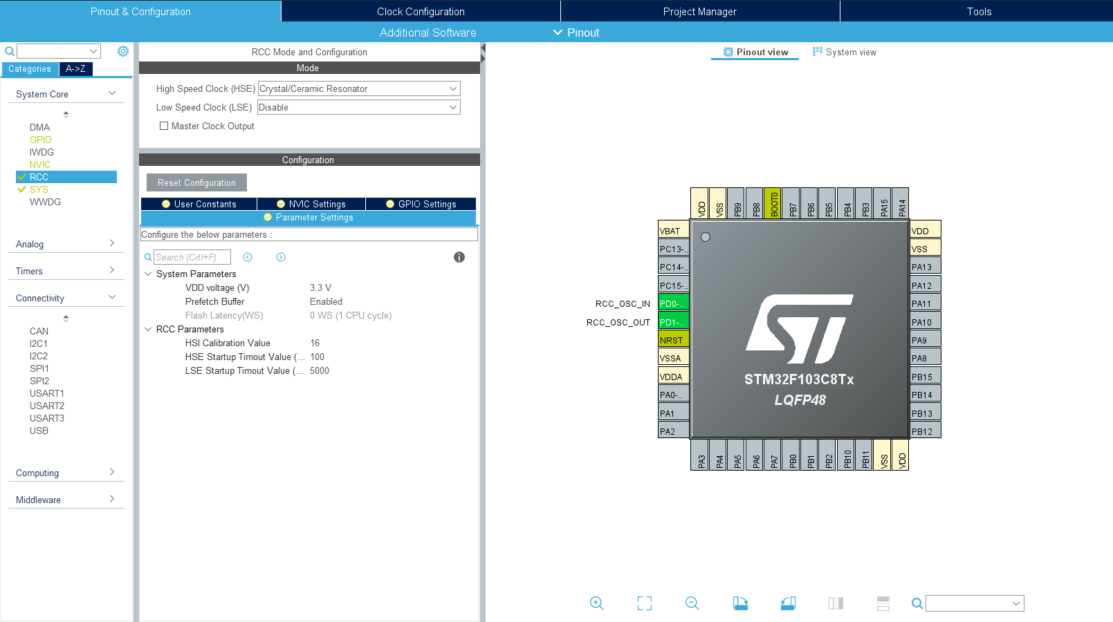
CAN Bus Peripheral in STM32 chip requires an external oscillator to work properly. So, we utilize the onboard 8Mhz crystal for our project. To enable external oscillator go to System Core > RCC and select Crystal/Ceramic Resonator in HSE
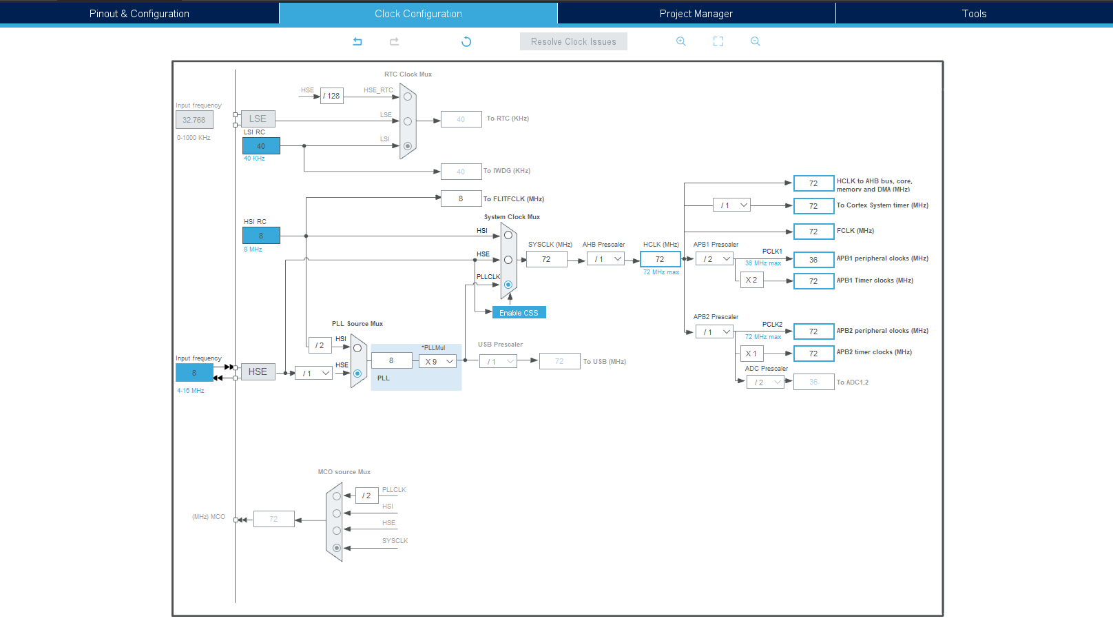
I run my STM32F103 at its maximum speed of 72Mhz so go to clock configuration and make the following changes
- Input frequency is 8Mhz
- HSE is selected in PLL Source Mux
- Change PLLMul to X9
- Select PLLCLK in System Clock Mux
- Change APB1 Prescaler to /2
After you make the above changes the configuration screen should look like the below image
Once this is done go back to the Pinout & Configuration view and in the categories side menu select Connectivity > CAN and check Master Mode.
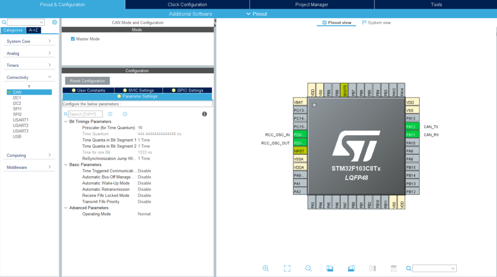
I need my CAN bus to work at 500kbps so i need to make changes in the Parameters Settings section. Ok, This part is gonna be a little bit tricky since it involves a bit of math but it is very easy once you get a hang of it
Our desired CAN bus speed is 500kbps ie. 500,000 bps The Time for one bit is 1/500000 Seconds ie. 2000ns So, we have to adjust Prescaler, Time Quanta in Bit Segment 1 and Time Quanta in Bit Segment 2 to get the required 2000ns in the Time for one Bit section.
I use Prescaler as 9 since it gives a round value 250.0 ns in Time Quantum
- Prescaler = 9
- Time Quantum = 250.0
- Time Quanta in Bit Segment 1 = 3 Times
- Time Quanta in Bit Segment 2 = 4 Times
- Time for 1 Bit = TQ + (TQ * TQ Bit 1) + (TQ * TQ Bit 2)
- Time For 1 Bit = 250 + (250* 3) + (250*4)
- Time For 1 Bit = 250 + 750 +1000 = 2000ns

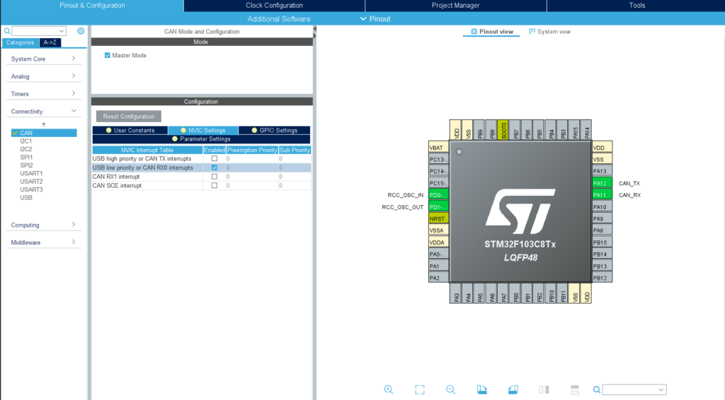
Once That is done go to NVIC Settings and check USB low priority or CAN RX0 interrupts to enable interrupt when CAN bus receives any message
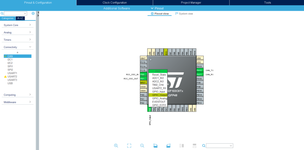
Okay, now we need some sort of indicator to check if data is coming in so we add a output on PA3
Alright , we are done with the configuration tool now save and generate the code. Go to Project Explorer > “Your Project” > Core > Src > main.c file. This file will have pre existing code which has been generated by the config tool.
We are going to add few Local variables like below
CAN_RxHeaderTypeDef rxHeader; //CAN Bus Transmit Header
CAN_TxHeaderTypeDef txHeader; //CAN Bus Receive Header
uint8_t canRX[8] = {0,0,0,0,0,0,0,0};  //CAN Bus Receive Buffer
CAN_FilterTypeDef canfil; //CAN Bus Filter
uint32_t canMailbox; //CAN Bus Mail box variable
Next, we are going to assign values to the canfil CAN bus Filter variable. you can write this code in main function before the while loop. This filter is used to filter out the incoming messages with their ID. This is especially useful when you need to accept messages from a particular node on the CAN bus. For now we are going to accept all messages so we set IdHigh and IdLow to 0
  canfil.FilterBank = 0;
  canfil.FilterMode = CAN_FILTERMODE_IDMASK;
  canfil.FilterFIFOAssignment = CAN_RX_FIFO0;
  canfil.FilterIdHigh = 0;
  canfil.FilterIdLow = 0;
  canfil.FilterMaskIdHigh = 0;
  canfil.FilterMaskIdLow = 0;
  canfil.FilterScale = CAN_FILTERSCALE_32BIT;
  canfil.FilterActivation = ENABLE;
  canfil.SlaveStartFilterBank = 14;
Next we are going to assign values to the Transmit header variable. The device ID is StdId and ExtID
  txHeader.DLC = 8; // Number of bites to be transmitted max- 8
  txHeader.IDE = CAN_ID_STD;
  txHeader.RTR = CAN_RTR_DATA;
  txHeader.StdId = 0x030;
  txHeader.ExtId = 0x02;
  txHeader.TransmitGlobalTime = DISABLE;
We have to initialize CAN Bus at this point and this has to be done before the while loop so take a look at below code
  HAL_CAN_ConfigFilter(&hcan,&canfil); //Initialize CAN Filter
  HAL_CAN_Start(&hcan); //Initialize CAN Bus
  HAL_CAN_ActivateNotification(&hcan,CAN_IT_RX_FIFO0_MSG_PENDING);// Initialize CAN Bus Rx Interrupt
Alright no we can send and receive CAN bus messages. To send CAN bus Message use the following code.
uint8_t csend[] = {0x01,0x02,0x03,0x04,0x05,0x06,0x07,0x08}; // Tx Buffer
HAL_CAN_AddTxMessage(&hcan,&txHeader,csend,&canMailbox); // Send Message
and now to receive message add this function to the end of your code
void HAL_CAN_RxFifo0MsgPendingCallback(CAN_HandleTypeDef *hcan1)
{
	HAL_CAN_GetRxMessage(hcan1, CAN_RX_FIFO0, &rxHeader, canRX); //Receive CAN bus message to canRX buffer
	HAL_GPIO_TogglePin(GPIOA, GPIO_PIN_3);// toggle PA3 LED

}
when the mcu receives data from CAN bus it fills up the canRX buffer and the data can be accessed from there.
- Full code Example can be found Here
Feel free to ask questions in the comments below 🙂


Hello.
I tested your can program.
It’s worked.
Very thanks.
I need to add 1 or several analog inputs to cob id.
1 analog into 2byte low and high byte. .
Can you change your program for my request?
Thanks best regards.
Hi, the best tutorial that I have read. Simple and objective.
Thanks.
Only good tutorial about this should be higher up on google!!!!
Thank you
Very useful tutorial! I assembled the device and connected it in my car.
One note! If you connect in the car, you don’t need to install a 120 Ohm resistor. CAN Bus terminating resistor is only needed on 2 terminal devices.
Добрый день. Подскажите пожалуйста, при помощи чего и какой программы считывать и отправлять данные?
thankyou so much for the help !, i would like to ask how can we check whether the project is succesful or not.. Thankyou in adavance.
Hi, work fine! Thank you.
Could you help me to set up for 100kbps baudrate? Please
[…] 実装するプログラムはこちらのサイトを基に設定しました。MCP2561を用いているため、起動時にPB11からSTBY信号をLowに落とす必要があるためその部分を追加しています。また動作していることがわかるようにPC13のLEDも光らせています。 […]
あなたの貢献に感謝します:)